Zigbee is a very cool technical. It makes point to point and point to multi point wireless communicate very easy. National Control Devices released ZR1x/ZR2x with Zigbee module. We will install Zigbee module in an electric outlet. It will be controlled by our timer software, Relay Timer R2x. The outlet can be Turn On/Off according the timers remotely.

Here are things we will use.
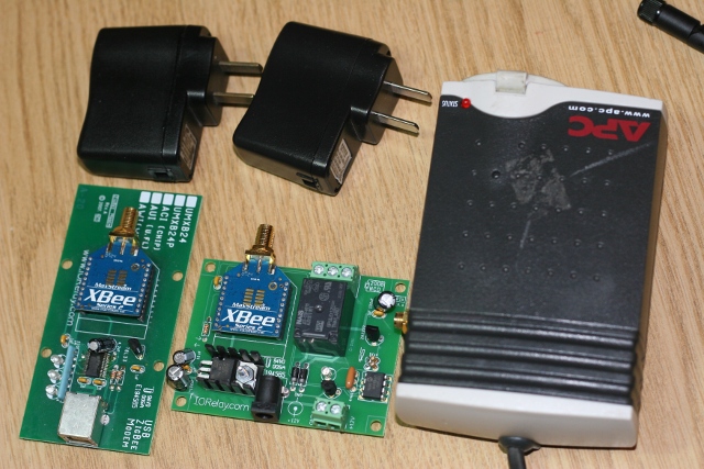
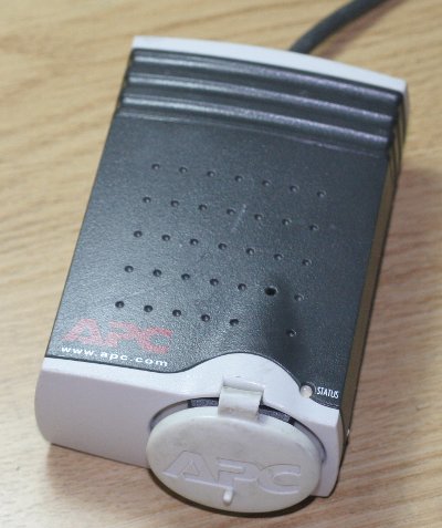
Car Power Adapter Outlet
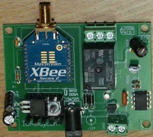
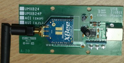
The voltage for ZR1x is 12v. We use two 5V mobile phone power adapter and connect them together to get 10v for ZR1x.
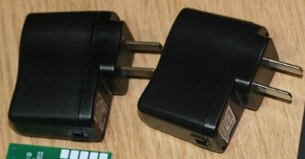
- Config ZR1x board and Zigbee modem with Comm Operator
Before we assemble the ZR1x with the outlet, we need configure and test the connection between ZigBee modem and ZR1x.
To make the two ZigBee modules talks to each other, they have to be in same protocol and using the same PAN ID. We will check Firmware version and destination of Zigbee module on ZR1x and Zigbee modem.
Let’s assume the Zigbee module on ZR1x named Z1 and Zigbee moduel on modem named Z2.
The default baudrate for setting of Z1 is 115200. The setting of Z2 is 9600. It is not necessary to set the same baudrate to Z1 and Z2. ZigBee module can talk in different baudrate. I’d like to change Z1 to 9600 so same configuration can work for both Z1 and Z2.
We will use Comm Operator for this.
Comm Operator v4.1 has plug-in for ZigBee. It is easy to test ZigBee application with it.
Put Z1 in modem board and connect it with computer.
Start Comm Operator, select the port that ZigBee modem used. The default setting for ZigBee modem is 115200, N, 8, 1
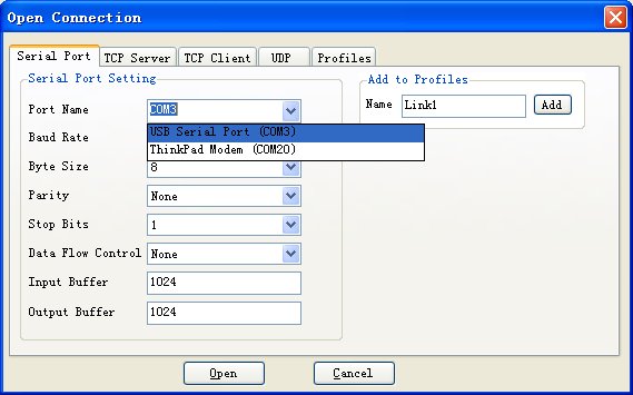
Goto [Tool]->[XBee Device Properties] to confirm the setting of Zigbee modem.
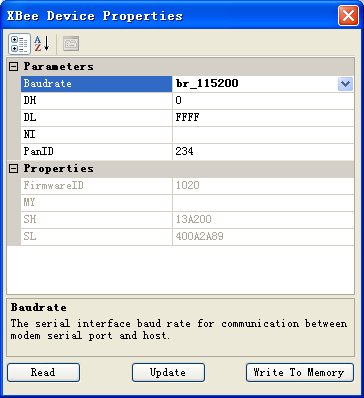
Set the destination to Z2’s address. You can find the 64bits address from Zigbee module. It can also be get from properties window. Set the baudrate to 9600.
Click the “Write to Memory” to update. Exit the property window and change the setting to 9600, N, 8,1.
Enter property window again.
Click “Read” to verify.
Exit Comm Operator.
Unplug the ZigBee Modem and unmount the Z1 module. mount Z2 to Zigbee Modem board and run Comm Operator again. This time, set Z2’s destination to Z1’s address and write to memory of Z2. Exit Comm Operate after this.
Mount Z2 to ZR1x and Z1 to Zigbee modem.
Power ZR1x.
Start Comm Operator and switch to NCD panel by [View]->[NCD].
Send 254, 0 to turn off and 254 ,1 to turn on. The ZR1x should turn on/off. So far, we have make this two Zigbee module talk to each other.
The next step is test ZR1x from RelayTimer R2x. It can be download from here.
Install it and Run configuration, set com port and baudrate with same port and baudrate we used in Comm Operator.
Switch to manual mode and turn it On/Off manually.
So far we have made everything work together. The next steps is connect the power to ZR1x and put ZR1x and power circuit boards in to car power adapter’s enclosure.
Here is the car power outlet adapater we use.
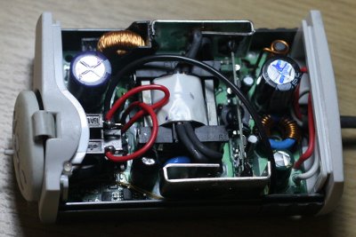
Let’s take everything out from it.

Connec the input 110 v power cable with ZR1x board. Then connect 12 v DC circuit board with 110 v power and Zigbee board.
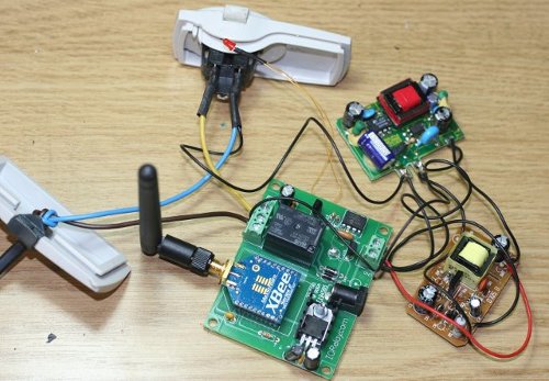
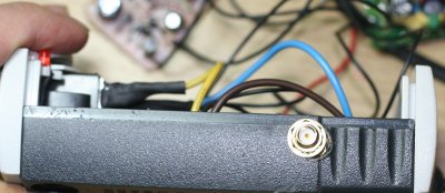
Drill a hold on side of car power adapter to fix the antenna.
We need to finish the bottom of circuit boards with insulation material to prevent them touch each other.
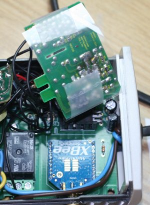
Put three circuit boards into the outlet adapter.
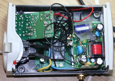
Control it with Relay Timer R2x.
So far, we have a smart outlet that can be turned on/off automatically!

